Product Description
(This module is included in the System B)
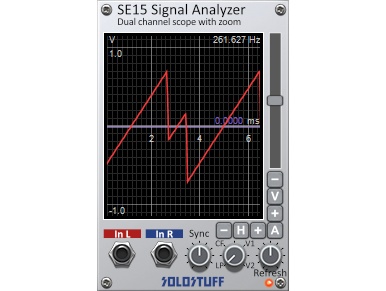
The SE15 signal analyzer is a dual channel scope with high zoom capability. The + and – buttons on the right side control the zooming for the horizontal and vertical axis. The H and V buttons will reset the zoom for horizontal and vertical axis respectively. The A button resets both. There is a vertical slider too.
The SE15 can sync to the red input channel to stabilize the display of the waveform. The blue input channel can not be synced*. Syncing complex waveforms is not a trivial matter. That’s why the module provides not one but four different sync modes (methods) to give a better chance for a successful syncing each method has it’s advantages and disadvantages. LP mode uses a lowpass method to try to sync. It can sync quickly and has a wide frequency range but suffers from horizontal (time) drift and jiter. CF mode uses a combination of filters, it’s a bit slower to sync but relieves some of the horizontal drift problems of LP. Modes V1 and V2 are correlation based methods. V1 can cope with dynamically changing pitches better. While V2 is better for dynamically changing waveforms but fixed pitch. Notice that V2 is sometimes particularly good for very complex waveforms as long as they don’t alias.
The sync knob controls the sync voltage level for modes V1 and V2 (LP and CF are not affected by this knob). Simply move the sync level up or down until the red channel display stabilizes to a comfortably clear waveform. The voltage of the sync level is also displayed in purple color above the purple sync line in the display. So you could use it as a measurement tool too. Remember, as long as the purple sync line crosses the red waveform. The display will sync to it.
The refresh frequency (or sync frequency) of the display is shown on the top right corner. This is NOT necessarily the frequency of the red channel waveform but often is when syncing simple waveforms.
The refresh knob also sets the refresh frequency of the display. However, this knob is active only if the red channel waveform frequency is too slow such that it’s slower than refresh knob frequency. In that case only, the refresh knob will determine the refresh frequency of the display. There is an LED under the refresh knob which will lit when the refresh knob is active.
Tip 1: If the red LED under the refresh knob is continuously flashing ON and OFF. This is almost always a bad setting and will always give jittery display. You either set the refresh to lower so that the syncing process dictates the display or set the refresh to higher so that the refresh dictates the display.
Tip 2: Displaying slow CV and LFO is usually better done using the blue channel and setting the refresh knob to a higher value until the display becomes smooth. Unless off-course you deliberately want to sync to the LFO speed.
You can lock the display refresh frequency to a certain value by clicking on it (top right). This will turn the text into red color. The refresh knob will be automatically set to that frequency and will become a fine tune knob. You can tweak it further to stabilize the waveform if it was drifting left or right. To unlock the frequency, click on the frequency again. This is useful when sync jiggles and can’t stay on particular frequency.
After locking you can right-click the frequency text to half the frequency or shift-right-click to double it.
Technical details:
High refresh rates (or syncing high frequency waveforms) consumes more CPU. This type of CPU will not show in your DAWs CPU meter!!. Instead it will show in the OS CPU meter (Task Manager) because it’s graphics related. Specially if you use many instances of the module in the same patch. Also, choosing a larger size for the GUI will also increase the CPU usage simply because there are more pixels to draw on the waveform display.
Locking the display frequency will help decrease CPU usage since it bypasses the sync process.
* It’s not possible to sync to both red and blue channels because the display will be inaccurate interms of the phase difference between the two channels.

